Energy
Designing homes to conserve energy and use it efficiently, from sources that cause least environmental harm.
Micro-hydro systems
Micro-hydro systems use flowing water to turn a water turbine that generates electricity in an alternator.
On this page:
- Micro-hydro system configuration
- Types of turbine
- Penstocks
- Static head
- Dynamic head
- Water flow rate
- Installation
- Electricity supply connection
- Environmental impact
Few houses have micro-hydro as an option – typically, only those on or near hills that have access to a stream that never dries up. However, because micro hydro works 24 hours a day 7 days a week, and can potentially provide all the power a house needs, these systems may be a better option than wind or photovoltaic generation.
Micro hydro systems are typically 0.5–1kW in size. More than one turbine can be installed depending on the water resource available. Think about location carefully – these systems can be noisy when operating.
Micro-hydro system configuration
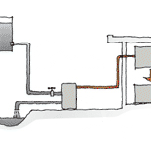
A micro-hydro system typically includes:
- a water source – a continuous flow of water such as a creek, stream, waterfall, small dam or spring-fed dam, with a drop in level, and that can be wholly or partially redirected through a micro-hydro system
- a turbine – turned by water acting on the blades of a runner or wheel
- a water intake or forebay – a catchment area that directs water into the turbine inlet pipe, while allowing sediment to settle and maintaining the water pressure head – examples of intakes include a dam, weir, bin, box or channel race from a stream
- a filter – mesh to catch leaves, sticks, stones and debris and stop them entering the water intake pipe, where they may otherwise block the pipe, reduce water pressure, cause rapid pressure fluctuations, or damage the turbine
- water inlet pipeline or penstock – the pipe transferring water from the water intake pipe to the turbine, which should be fully submerged at the inlet
- water outlet pipeline or tailrace or draft pipe – the pipe discharging water from the turbine back to the stream or creek – note that a water outlet pipeline may not be required with an impulse turbine as it generally sprays out water
- alternator – alternating current is generated by rotor windings connected to the shaft from the turbine turning inside the stator windings of the alternator body
- rectifier – converts AC to DC for electricity that is being sent to a battery storage system – the generator initially produces AC, but is called a DC generator if the output electricity is immediately sent through the rectifier
- electricity cables –transfer the electricity from the generator to the electricity supply or storage system
- a spill way or bypass – for excess water to be able to flow past the system or allow the system to be shut down.
Types of turbine
The two main types of micro-hydro turbine are
- impulse turbines
- reaction turbines.
The system may also include an inverter to allow connection to the grid.
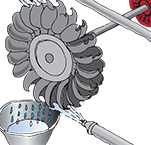
- An impulse turbine
Typical impulse turbines operate when a jet of water is directed at cups mounted around the edge of a wheel. These turbines are sometimes called Pelton wheels after their inventor. They run in an open (i.e. not sealed) unit, and with an open-air connection to the water inlet pipe. An impulse turbine may or may not have a connection to a water outlet pipe. This type of turbine needs protection from water flooding. They are typically installed in higher water head applications, of up to 10 metres water pressure head, and are more common than reaction turbines for domestic applications.
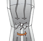
- A reaction turbine
Reaction turbines have runners as their turbine blade unit. They are fully immersed in the water flow, and have a sealed case around the runner blade unit and a closed connection to the water inlet and water outlet pipes. They are typically installed in low water head applications.
Penstocks
The penstock inlet should be located as low as possible in the water so that it remains submerged when water levels are low. However, if it is too low, it may get blocked by sediment building up in front of it. An air vent may be required near the intake to prevent damage if the intake blocks and a vacuum is created. Penstocks must slope downwards or an air lock may form, affecting performance.
A penstock should include a shut-off valve to stop water flow during maintenance of the turbine. They must be strong enough to resist the design water pressures and be protected from rapid starting and stopping of the water flow. They must also be protected from impact damage and exposure to the sun by being buried or enclosed in a box structure.
Static head
The static head (or gross head) is the vertical distance between the water level at the intake and the discharge point. Both these levels are where the water has contact with air. The water discharge level for an impulse turbine is where the water leaves the inlet pipe and enters the turbine. For a reaction turbine, the discharge level is where the water is discharged from the outlet pipe.
The static head increases as the water level at the intake increases. Minimum static head is where the water level aligns with the top of the inlet pipe – keeping in mind the inlet pipe entry needs to remain submerged.
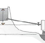
- Micro-hydro static head
The static head (or gross head) is the vertical distance between the water level at the intake and the point at which the water is discharged.
Dynamic head
The dynamic head (in metres) is the static head (or gross head) less the losses in the pipework. The losses are summed and converted to a pressure head value in metres. The dynamic head is therefore the actual amount of water pressure head available to generate electricity.
Friction losses should be minimised by:
- short pipe lengths
- large pipe diameters
- few pipe bends
- high-radius pipe bends
- steep gradient.
Friction losses will also occur when the intake gets blocked.
Water flow rate
The water flow rate (in litres per second) is the amount of water moving through a pipe in a specific period of time. As the water flow rate increases, the turbine spins faster and more electricity is generated.
The main water flow will typically vary during the year and between years and may be dependent on:
- seasonal rainfall
- snow and ice melt in the mountains
- cycles of flooding or drought
- blockages higher up the water source.
Micro-hydro generators work best where there is reasonably continuous water supply, giving a reasonably constant static head. It is important to determine what the average year-round water level is at the intake, as this will be used for the static head to determine the year-round power output.
Any intake water storage system (e.g. dam, bin) with a reasonably constant water flow into it will maintain a consistent or equilibrium water level. When storage water levels are:
- higher, the generator flow rate increases until the level drops
- lower, the generator flow rate decreases until the level rises.
This equilibrium water level will be the design static head for the system. However, it can be difficult to determine initially as it is related to the water flow rate through the generator and in the main water source. The water flow rate at a site is not simple to measure and may require the temporary installation of a weir. The water flow rate through the generator can be determined by iterative design techniques for different water heads.
Calculating potential generation from micro-hydro
The amount of electricity that can be generated depends on the water flow, the change in height between inlet and outlet (the head), and the efficiency of the system.
For example, if a 20 litre container takes 1 second to fill, the flow is 20 L/s.
Variations in efficiency must be considered – units can have an efficiency of 30–70%; for this calculation, 50% will be assumed.
Finally, the effect of gravity is taken into account, using a gravity constant of 9.8 m/s2.
A rough calculation is:
Flow (L/s) x head (m) x efficiency (%) x gravity constant (9.8 m/s2) = power (W).
Or:
20 L/s x 15 m x 0.5 x 9.8 m/s2 = 1.47 kW
The same power generation can potentially be achieved with a low head and high water flow rate (gently sloping terrain with a large water catchment) or a high head and low water flow rate (steeper terrain with less water catchment area).
Micro-hydro units generating 5kW or more are available, but for a single household, units of 1–1.2 kW are more common.
If there is seasonal variation in water flow, this can also be factored in to work out potential energy output over a year. The power output calculated above is multiplied by the number of hours in a year (8,760 h) and a capacity factor (a percentage by which usage is reduced) – in this case, 50%.
The energy calculation is:
1.47 kW x 8,760 h x 0.5 = 6,438 kWh.
Installation
The micro-hydro system:
- will require a building consent and a resource consent
- should be installed as close as possible to the electricity supply or storage system, to reduce line power losses
- must withstand the water loads
- must have protection from impact, particularly for the less solid pipework
- generally requires little maintenance as it has few moving parts – the main issue is normally having to replace the alternator brushes and flushing the turbine
- may need regular cleaning of the filter, depending on the amount of debris in the water supply
- must incorporate a means of restricting the natural outward flow of water to build up reserve capacity
- must incorporate a bypass overflow in case of flooding of the reservoir.
Electricity supply connection
Electrical power from the micro-hydro generator system can be available continuously at consistent output levels. The output AC may be:
- transferred as AC to the building for immediate use, via a controller that gives a 240V AC at 50 Hz power supply, or
- converted by a rectifier to DC for storage in batteries.
The choice between AC supply and DC storage is dependent on the reliability of electrical generation and the capacity of the generator to meet peak demand.
Options include:
- output all the AC directly to the building, where electrical generation is continuously guaranteed and generator capacity is greater than peak demand
- output some of the AC directly to the building, with the rest converted to DC storage, where peak demand is occasionally a little higher than generator capacity or there is occasional reduced electrical generation
- convert all of the AC to DC storage, where electrical generation is inconsistent, or peak demand greatly exceeds generator capacity.
Micro-hydro schemes work most effectively where a home is energy-efficient, and where other options reduce electricity demand, such as using solid fuel heaters for space heating and solar or wet-back units for water heating.
Environmental impact
Micro-hydro generator systems have an impact on the water course. They may potentially affect:
- plant and fish life in the water
- plant and animal life beside the water
- other users of the water further down stream
- the stability of the surrounding land through the excavation for a reservoir if there is one.
There are many design possibilities that can be chosen to reduce environmental impact. For example, if a weir or dam is required, a fish ladder can be included so that fish that migrate up-river are able to pass the weir.
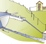
- Water diversion for micro-hydro system
Even small dams can have a significant impact both downstream and upstream as they are a break-point in the water system. It is therefore more usual, and more acceptable to the consenting authorities, to temporarily divert a portion of the main water flow into the micro-hydro generator. The water is returned downstream, and there is no block in movement up or down stream. In general, the amount of water used for the micro-hydro system should be no more than 50% of the minimum seasonal flow rate of the water source.
Updated: 22 September 2020


