Water
Water use, sustainability, and efficiency by choosing quality systems and materials, and providing environmentally friendly solutions.
Backflow prevention
The water supply system must be designed and used to prevent contamination from backflow.
On this page:
- Causes of backflow
- Code requirements
- Using an air gap to prevent backflow
- Backflow prevention devices
- Installation requirements
- Testing
Backflow is the unplanned reversal of flow of water (or water and contaminants) into the water supply system.
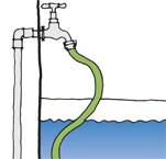
For backflow to occur, there must be a physical connection, or cross-connection, between the water supply and any delivered water or contaminant. A common situation is the end of a garden hose submerged in a bucket or other container of liquid. Backflow can also arise from appliances, pools, and water storage tanks such as header tanks and rainwater tanks.
As well as using the methods described below to minimise the risk of backflow, advise building owners to take simple precautions such as not submerging garden hoses or spray heads from showers and sinks, and always turning off the water supply at the tap when it is not being used.
Causes of backflow
Backflow is caused by a difference in pressure and may occur due to:
- backsiphonage – the supply pressure is less than the downstream pressure, allowing water to be pushed in the wrong direction
- backpressure – for example, insufficient relief of pressure in a vessel where water is heated.
Backflow can only occur where there is a connection or cross-connection. Cross-connections can occur in any situation where fixtures are connected directly to the main supply such as:
- irrigation systems
- dishwashers
- washing machines
- coffee machines
- swimming pools, spa pools or ornamental pools that are filled by hose
- water softeners
- pesticide and fertiliser attachments for hoses
- fridges and icemakers
- bidets
- retractable spray outlets to tubs and sink
- flexible shower hoses
- storage tanks.
Code requirements
Building Code Clause G12 Water supplies requires that potable water supply must be protected from contamination and installed in a manner that avoids the likelihood of contamination within the system.
Acceptable Solution G12/AS1 requires backflow prevention to be provided where it is possible for water or contaminants to backflow into a piped potable water supply. Backflow can be prevented either through an air gap or a backflow prevention device (see below).
The Acceptable Solution also provides that there must be no likelihood of a cross-connection between a private water supply (such as a rainwater tank) and mains water supply.
Responsibility for preventing backflow may rest with:
- the network utility provider who may install a backflow prevention device as part of the meter assembly, or
- the individual property owner whose responsibility it is to comply with the requirements of the network utility provider and the Building Code, and to protect building users.
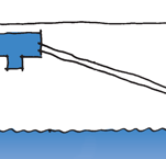
Using an air gap to prevent backflow
In most situations, an air gap is the most cost-effective and reliable form of backflow prevention.
An air gap should be used to prevent backflow from rainwater tanks and other water supply tanks into the mains-supplied water system. Air gaps should also be used to prevent backflow of contaminants from all appliances and fixtures that are connected to the water supply.
For swimming and spa pools, provide a dedicated water supply with an approved air gap.
Acceptable Solution G12/AS1 requires that the air gap must be the greater of 25 mm, or twice the diameter of the supply pipe.
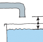
- Principle of air gap used for backflow prevention
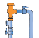
If mains supply is used to top up a private water supply, backflow can be prevented by using a floating weight can be used to operate a valve, ensuring that the maximum water level always remains at least 25 mm below the mains inlet. Alternatively, a double non-return valve can be used.
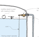
- Mains water supply top-up valve and air gap backflow prevention
If a piped supply is used to top-up the rainwater storage tank, a simple commercially available floating switch will ensure that top-up water is added only when the level in the tank is low. A float valve should not be used because it will add piped water whenever there is any draw-off.
- Double non-return valve installation to prevent backflow contamination of a potable water supply
If there is any direct connection between mains supply water and a rainwater collection system, then a means of preventing backflow, such as a double non-return valve, must be designed into the system.

Backflow prevention devices
If the system is a high pressure system and a pipe is directly connected to an appliance or sanitary fixture, it may not be possible to use an air gap. In this case, a backflow prevention device must be installed.
The appropriate device for a particular installation will depend on the:
- hazard level of any potential contaminant
- potential for cross-connection
- type of backflow expected
- physical limitation of the device and the environment.
Cross-connections are rated according to Building Code Acceptable Solution G12/AS1 to three hazard levels:
- High – this has the potential to cause death
- Medium – this would endanger health
- Low – this is a nuisance but does not endanger health
Generally, the higher the hazard, the higher the risk, so the safer the device must be.
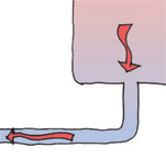
Vacuum breaker
A vacuum breaker contains a float disc and an air inlet port. Under normal water flow, the float disc closes off the air inlet port, but if the normal water flow is interrupted, the float drops, closing off the system against backflow and, at the same time, opening the air inlet port.
A variety of vacuum breakers are available:
- Atmospheric vacuum breaker
An atmospheric vacuum breaker (AVB) is one of the simplest and least expensive backflow prevention devices and can provide excellent protection against backsiphonage. It consists of a gravity plunger or float disc that is forced upwards when the supply pressure is turned on, thus sealing off the atmospheric vent overhead. As soon as the supply is interrupted or terminated, the float drops down and opens the downstream pipework to atmosphere. There must be sufficient pressure to fully lift and seal the float on the vent, so it is not suitable for use on very low pressure systems.
- Hose connection vacuum breaker
A hose connection vacuum breaker (HCVB) is a specialised type of atmospheric vacuum breaker designed to attach directly to the hose tap. It has a spring-loaded check valve that seals against an atmospheric outlet when the water supply is turned on. When the supply is turned off, the device vents to atmosphere, thus protecting against backsiphonage conditions. It is non-testable and should not be used as protection against backpressure or be subject to continuous pressure (2 hours maximum is permitted), i.e. no control valves should be located downstream of the device.
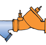
- Pressure vacuum breaker
A pressure vacuum breaker (PVB) evolved due to a need to have a vacuum breaker that that can be subject to constant pressure and is able to be tested in line. It is similar to the atmospheric vacuum breaker except that there is a spring to hold the disc float in the open position during normal operation. They have two isolating valves and two cocks for testing, one for each chamber. These devices can be used under constant pressure but do not protect against backpressure. They must be at least 300 mm higher than any downstream piping.
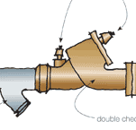
Double non-return valve assembly
- Double non-return valve assembly
Essentially, a double non-return valve assembly (also known as a double check valve assembly or DCVA) consists of two independently operated non-return valves within one body. One non-return valve simply acts as a back-up. Because there is a risk that both valves will fail at the same time, regular testing is imperative, and the device is limited to use in medium and low hazard situations. This valve will protect against backpressure and backsiphonage but is not fail-safe. Because of the spring pressures, there can be a significant reduction in pressure (up to 40 kPa) across this device.
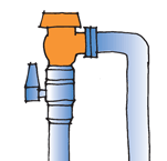
Reduced pressure zone device
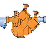
- Reduced pressure zone device
This backflow protection device incorporates two independently-acting, spring-loaded check valves separated by a differential pressure relief valve. Pressure between the two valves is lower than the supply pressure during normal operation. If either check valve leaks, the pressure relief valve will open, discharging water out of the system.
This device provides the maximum protection of any valve and can be used in high hazard situations.
Backflow prevention device | Typical applications |
Air gap | Taps, sinks |
Vacuum breakers (VB) | Industrial plants, cooling towers, laboratories, laundries, swimming pools, lawn sprinkler systems, fire sprinkler systems |
Double check valve assembly (DCVA) | In-house pumps, elevated tanks, non-toxic boilers |
Reduced pressure backflow assembly (RPBA) | Industrial plants, hospitals, morgues, chemical plants, irrigation systems, pumps, elevated tanks, boilers, fire sprinkler systems |
Installation requirements
All backflow prevention devices require a building con/ must be:
- installed by a registered plumber
- installed as near as practicable to the potential point of contamination
- protected from physical and frost damage
- isolated from corrosive or toxic environments
- installed above surrounding ground level so that leakage from air ports and discharge ports is readily visible
- installed in a position and manner to be accessible for maintenance and testing
- fitted with a line strainer upstream to prevent particles in the pipework from rendering the device ineffective
- attached only after the pipework has been flushed
- installed without the application of heat.
Testing
Backflow prevention devices may be testable or non-testable. Their use in a particular situation depends on the degree of hazard. Non-testable devices may only be used on low-hazard rated systems.
Testable devices must be tested on installation and at regular intervals to the standard set down by Acceptable Solution G12/AS1: 3.7 Testing. Non-testable devices should be checked every 2 years maximum.
Updated: 12 September 2016